Troubleshooting
Related failure
When the [Connect USB3.0] sign is displayed in the lower left corner of the software, it means that the software has recognized the matching camera and can work normally. If not, please refer to Appendix 1.

Image blurry, error
a) When the camera is working, it is necessary to keep the camera and the measured object relatively still. If the object moves, it will cause the three-dimensional image to be blurred, or have a striped shape, or be completely wrong. At this time, please check the working environment of the equipment to eliminate environmental vibration.
b) In addition, inaccurate focus of the camera/projector in the device will also result in blurred shooting results. If this happens, please contact the supplier and have it re-adjusted by a professional.
Coarsely adjust shooting distance
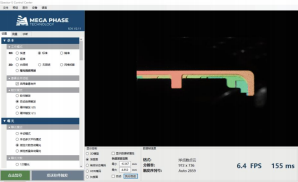
Adjust the distance between the measured object and the camera according to the product description parameters. The camera shoots continuously. In the 2D white lighting mode, you need to adjust the object distance while checking the image clarity. See the diagram below for details.

Finely adjust shooting distance
Adjust the shooting mode to 3D mode. After shooting and displaying the 3D image, select "Depth Map" in the option bar below the display area. Move the mouse to any position on the depth chromatogram. The Z value will be displayed in the lower left corner (as shown below). In the continuous shooting mode, the Z value will be continuously updated, and the distance between the measured object and the camera will be adjusted until the Z value of the measured surface point is close to "0". At this time, the image quality is the best and the object distance is the optimal measurement distance. .
Abnormal maintenance of camera humidity
Explain
The unloading camera is designed according to IP67 and has passed IP65 certification; Each interface is designed with protective measures. When in use, the interface is normally locked to achieve IP65 protection; (Note: the USB port has air holes, and this position needs to be locked to achieve; the rest of the interface can achieve IP65 protection in any state)
Production protection:
The factory environment is constant temperature and humidity, temperature and humidity are monitored, and through the process and process, it is guaranteed that there will be no abnormal condensation when the camera leaves the factory; Shipment quality inspection, image quality confirmation without condensation;
Transport protection:
Double-layer protection: USB interface sealing protection measures; moisture absorption protection inside product packaging;
Possible causes of humidity anomalies
If the camera is deployed or stored in a humid environment, after removing the seal of the USB interface, and the cable is not connected for a long time, moisture may enter the camera through the USB interface, resulting in abnormal condensation of the camera; The abnormal picture is as follows: (camera lens) (image to be updated) Display on exception image: (image to be updated)
You can judge and locate it through the following steps:
The main abnormal phenomenon: large areas of 3D point clouds are missing, generally showing a pattern of weakening with increasing distance from the middle of the field of view.
Troubleshoot abnormal working of the projector: Observe the projection stripes on the workpiece with the naked eye and confirm that the projection stripes are working normally.
Locate the abnormality on the camera side: through the Viewer, confirm that the 2D image of the camera is abnormal, and presents the phenomenon of fogging and blurring; generally presents the law of weakening with the increase of the middle distance of the field of view
Locate the camera lens abnormality: Observe the camera lens protective glass with the naked eye to confirm the abnormality;
Elimination method
The camera is placed in a dry environment and kept powered, but not connected to the USB port (keep the air hole open), for two or three days, it can be eliminated;
Suggestion: How to reduce the occurrence of exceptions
After uncovering the sealing protection measures of the USB interface, connect the USB cable as soon as possible to avoid exposure of air holes for a long time;
After uncovering the sealing protective measures of the USB interface, for long-term storage, please store it according to the category of precision measuring instruments, dry, constant temperature, and constant humidity; when storing, store it with a cable; or use simple measures to seal the USB port;
Run log export
Click [Diagnostics]-[Export Diagnostics Report] to export the running log. See 3.2.3.3 for details.
Appendix 1 Exception handling
| Serial number | Abnormal situation | Possible Causes | Solution |
|---|---|---|---|
| 1 | Camera cannot connect to PC | 1、The USB is not firmly connected; 2、The driver is not installed correctly; | 1. Re-plug the USB cable, power off the camera and restart; 2. Run the installation batch program; |
| 2 | USB is displayed as USB2.0 | The USB is not plugged firmly, the USB driver is not installed, or it is plugged into the USB2.0 interface. | Confirm whether the USB3.0 driver has been installed, re-plug it and then power off and restart the camera. |
| 3 | The camera cannot capture images normally | The camera is subject to external interference, or internal malfunction | Stay away from interference sources or perform shielding and then restart the camera. |
| 4 | After installing the SDK, the batch program does not work properly | The computer has security restrictions | Manually install USB driver, .Net framework4.0, C++2012 and other programs |
| 5 | After installing the SDK, it prompts that the graphics card driver is not installed or the image cannot be displayed properly. | The graphics card driver is not installed or installed incorrectly | Reinstall the integrated graphics driver or discrete graphics driver |
| 6 | The camera does not take an image when sending a trigger signal | USB connection unstable | Plug and unplug the USB data cable again, or replace the USB data cable |
| 7 | The camera does not capture images when sending an I/O trigger signal. | The IO cable is not connected properly or the wiring is wrong. | Recheck the IO circuit according to the wiring diagram of the IO line |
When the camera is deformed due to external force, the glass is broken, or is unable to work due to other unidentified faults, please contact Shengxiang Technology for replacement or repair.