Device installation
Camera and accessories list
Conditions required for the camera to work properly:
- Sizector® 3D Camera S028 Product Series or S162 Product Series.
- Power Adapter
- Power supply and I/O control cable (two-in-one power supply and I/O control)
- USB3.0 High speed data transmission line
In addition, users need to prepare their own computers with Windows 7 and above 64-bit operating systems.
Camera accessories description
It is recommended to use product-specific accessories. Using other different types of accessories may cause the 3D camera to not work properly.
Main parameters of power adapter
- Input :100-240VAC,50/60Hz,1.4A
- Output:24V—5.0A,120W MAX
Using a power adapter with other voltages and currents may cause equipment damage or abnormal conditions such as failure to capture images. For the dimensions of the power adapter and power cord, please refer to : Dimensional parameters of power adapter and cable body
IO control cable wiring instructions
Provide the camera with the IO port wiring instructions for the external hard trigger. For more information please see Appearance and dimension parameters of the IO control cable。
USB3.0 high-speed data transmission line
Camera connection control and data transmission can be realized through the standard USB3.0 interface. For details of the supplied USB3.0 high-speed data transmission cable, please refer toDescription of USB3.0 high-speed data transmission line。
Installation steps
There are three Φ5.3mm through holes on the front of the camera, as shown in Figure 2.1, the following installation methods are recommended: ①Use three M5×60mm bolts on the front (the thickness of the fixing bracket needs to be considered). ② Use 3 M6 (length less than 12mm + bracket thickness) screws on the back to fix it on the stable bracket. Please refer to the camera size chart Product parameters and appearance size chart.

Mark:
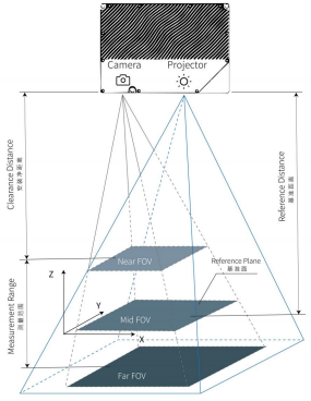
- It should be ensured that the measured surface of the object is placed near the 0 plane of the camera to the greatest extent, as shown in Figure 2.2;
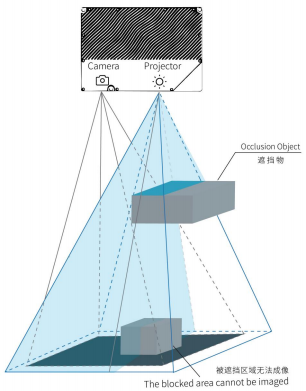
- Observe the direction of the camera projector to avoid light being blocked, as shown in Figure 2.3;
- Avoid the measured area being in a dead zone;
Camera external interface definition
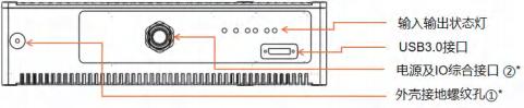
The interface description of the camera body is shown in the figure below:
Device status
Device state (DeviceState) includes the following five types:
- Disconnected: No communication operations can be performed at this time.
- UnderInit: At this point the register value can be set, but the device will not perform any operation.
- StandBy: The device is idle and the device can take new shots.
- UnderExposure: The equipment is being exposed. At this time, you should avoid moving the measured object or causing vibration, otherwise it may increase the error of the 3D point cloud.
- UnderTransfer: The device has completed exposure and is transferring the 3D point cloud to the PC. At this time, the measured object can be moved to shorten the cycle time.
Users can obtain device status through query or callback function. It is recommended to obtain through callbacks, but frequent queries should be avoided. In addition to the software interface, the LED status can also reflect the status of the device:
- Blinking yellow/green LED (5Hz): The device is initializing
- Blinking red LED (5Hz): The device has an error during initialization
- Blinking yellow LED(5Hz): The camera is under thermal protection
- Blinking green LED (5Hz): The camera has been initialized and is waiting to be connected
- Steady green LED: The camera is connected and ready to capture images.
- Steady red LED: the camera is exposing
①* The camera ground screw hole, it is recommended that the camera ground wire be connected to a reliable ground wire at the other end to prevent damage to the camera due to leakage of surrounding equipment, unstable power supply voltage, or lightning strikes.
②* The camera's power supply & IO integrated 17-pin interface includes two Input holes and two Output holes. When plugging in, pay attention to the direction of the power cord plug and this interface.
Reset
When the product is abnormal and needs to be reset, the enumeration is as follows::
| Serial number | Abnormal situation | Possible Causes | Solution |
|---|---|---|---|
| 1 | Camera cannot connect to PC | 1、The USB is not firmly connected; 2、The driver is not installed correctly; | 1. Re-plug the USB cable, power off the camera and restart; 2. Run the installation batch program; |
| 2 | USB is displayed as USB2.0 | The USB is not plugged firmly, the USB driver is not installed, or it is plugged into the USB2.0 interface. | Confirm whether the USB3.0 driver has been installed, re-plug it and then power off and restart the camera. |
| 3 | The camera cannot capture images normally | The camera is subject to external interference, or internal malfunction | Stay away from interference sources or perform shielding and then restart the camera. |
For more possible abnormal situations and handling methods, please refer to Appendix 1.
Notice:
- This product must be installed by professionals, please be sure to follow the operating specifications to avoid injury and safety problems.
- Do not try to open or repair the device, wrong operation will cause permanent damage to the device.
- After the equipment is installed, please do not move easily or disassemble the equipment parts
- Carefully read the relevant documentation before testing or operating.
- The device should be installed on the fixed bracket to avoid severe vibration.
- In order to ensure the consistency of detection, please ensure that the temperature and humidity of the detection environment are relatively constant.
- Use professional tools to maintain and clean the lens to avoid damage to the lens.
- Looking directly at the high-brightness blue light emitted by the projector for a long time may be harmful to the eyes.